Over 10 years we help companies reach their financial and branding goals. Engitech is a values-driven technology agency dedicated.

Gallery

Contacts

411 University St, Seattle, USA

engitech@oceanthemes.net

+1 -800-456-478-23

Blog Technology
I/O header

How to wire I/O Header on Motherboard?

How to wire all the I/O Header on Motherboard

image source: corsair.com

Introduction to I/O Header on Motherboard

Navigating through many cables and connectors can be overwhelming when assembling your PC. One particular set of wires integrated into your PC’s case that often confuses is the one dedicated to connecting the front panel I/O (input/output) ports. These ports typically include USB ports (Type-C and Type-A), audio jacks, status LEDs, and power/reset buttons.
This concise guide will provide essential insights on correctly connecting these cables, accompanied by illustrative photo examples to simplify the process.

Different type of Plug for Motherboard

In this exploration, we’ll shift away from the conventional illustrations commonly found in quick start guides. Instead, we’ll provide accurate pictures of various plug types, offering a more impactful and visually effective learning experience. Let’s delve into the details for a comprehensive understanding.

I/O header front panel connectors motherboard connect USB-ports Type-C Type-A audio jacks status LEDs power-on reset

USB 3.0 Gen 1 to 2x USB Type-A

front panel connectors motherboard connect USB-ports Type-C Type-A audio jacks status LEDs power-on reset

USB 3.1/3.2 Gen 2 to USB Type-C

 
front panel connectors motherboard connect USB-ports Type-C Type-A audio jacks status LEDs power-on reset

HD Audio to 3.5mm combined headset/microphone jack

front panel connectors motherboard connect USB-ports Type-C Type-A audio jacks status LEDs power-on reset

Power SW to power button

front panel connectors motherboard connect USB-ports Type-C Type-A audio jacks status LEDs power-on reset

Reset SW to reset button

front panel connectors motherboard connect USB-ports Type-C Type-A audio jacks status LEDs power-on reset

Power LED + and Power LED – to the power LED

Different type of I/O Header on Mother Board

The vocabulary of these ports may vary across different motherboard models, but the essence of the connector remains constant. To navigate through this, consulting your motherboard’s manual is vital in identifying the specific locations of each port. It’s crucial, especially for USB ports, as their configurations can differ.
Ensuring functionality for all 4 Type-A ports on the case requires two USB3.0 Gen 1 connectors to be available. Refer to your motherboard’s manual for precise port locations and configurations.
Consider PCIe expansion cards that provide an additional internal port in scenarios where your motherboard only accommodates one connector. Alternatively, explore using an adaptor capable of transforming a USB 2.0 port (depicted below) into a USB 3.0 Gen 1 port. Note that when converting a USB 2.0 port, you’ll be sacrificing the maximum speed of the I/O panel ports, limiting them to USB 2.0 speeds. Stay informed for optimal I/O header utilization.

front panel connectors motherboard connect USB-ports Type-C Type-A audio jacks status LEDs power-on reset

USB 3.1/3.2 Gen 2 to USB Type-C

 
front panel connectors motherboard connect USB-ports Type-C Type-A audio jacks status LEDs power-on reset front panel connectors motherboard connect USB-ports Type-C Type-A audio jacks status LEDs power-on reset

USB 3.0 Gen 1 to 2x USB Type-A

front panel connectors motherboard connect USB-ports Type-C Type-A audio jacks status LEDs power-on reset

HD Audio to 3.5mm combined headset/microphone jack

 
front panel connectors motherboard connect USB-ports Type-C Type-A audio jacks status LEDs power-on reset

Pins to connect the power switch, reset switch, and power LED

front panel I/O header connectors motherboard connect USB-ports Type-C Type-A audio jacks status LEDs power-on reset

USB2.0 Port to 2x USB Type-A.

Avoid Motherboard Damage: A Guide to Safe I/O Header Connections

Caution: Incorrectly plugging cables into your motherboard can lead to severe damage. Feel free to contact our support team if you are still deciding. We’re here to guide you through the process and ensure a smooth connection.

Connecting most plug types, including USB 2.0 and USB 3.1/3.2 headers, is straightforward. These headers feature a notch and closed pins, ensuring they can only be inserted in one direction. Take a close look at both the plug and the socket to confirm the proper alignment before insertion. This simple precaution can prevent potential issues and safeguard your motherboard from damage.


I/O header
I/O header front panel connectors motherboard connect USB-ports Type-C Type-A audio jacks status LEDs power-on reset

With the USB3.1/3.2 header we have marked out the pins used in yellow as well as the cut out in the housing that you will find the corresponding notch to on the plug itself. The pin location marked in red is missing from the header and closed shut on the plug itself.

front panel connectors motherboard connect USB-ports Type-C Type-A audio jacks status LEDs power-on reset

When dealing with the AUDIO header, the process is akin to other headers but with a distinctive characteristic. Unlike some titles, the AUDIO header typically lacks a guiding notch or housing, presenting a direct arrangement of pins on the board. In such cases, observing the closed pin on the plug itself becomes crucial for proper alignment during insertion. Paying close attention to this detail ensures a secure and accurate connection of the plug to the AUDIO header, enhancing the overall functionality of your system.

I/O header
front panel connectors motherboard connect USB-ports Type-C Type-A audio jacks status LEDs power-on reset

Connecting the Main Power I/O Header

Embarking on the journey of assembling your PC? Let’s kick things off by delving into the four most crucial connections that ensure seamless functionality:

  1. Power button connector = POWER SW (+PW-)
  2. Reset button connector = RESET SW (-RES+)
  3. Power LED lights connector = POWER LED + & POWER LED – (+PLED-)
  4. HDD LED lights connector = POWER LED + & POWER LED – (+PLED-)

These pin-type plugs play a vital role in hooking up the power button, reset button, power LED, and sometimes the HDD LED. Many motherboards feature markings to guide you in the right direction, but consult your motherboard manual for accurate placement if absent. While polarity markings may be present for all pins, the critical ones are those for the power LED, HDD LED, and speaker. Clicky-type power buttons and reset switches work either way, as they aim to bridge two pins for turning on or resetting the PC. If plugs are marked with a polarity indicator, follow suit for proper connection.

FAQs on I/O header

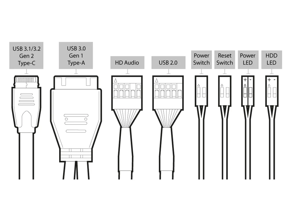
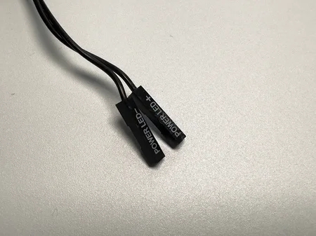
Q: Can I customize the LED colours for the Hard Drive Activity and Power LEDs?
A: Explore your customization options in LED colours, adding a personal touch to your system’s aesthetics. Most motherboards support customization through dedicated software.

Q: Is it safe to disconnect pin 8 (No Connection)?
A: Absolutely. Pin 8, labelled ‘No Connection,’ is intentionally left unused. Disconnecting it won’t impact your system’s performance, ensuring flexibility in your motherboard setup.

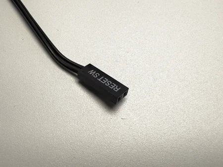
Q: How do I troubleshoot issues with the Reset Switch?
A: Troubleshooting the Reset Switch involves checking the pin connections and ensuring they align with the motherboard manual. Additionally, inspect the switch for physical damage.

Q: Can I replace the +5 V DC pin if damaged?
A: While it’s theoretically possible, it’s recommended to consult the motherboard manufacturer or a professional technician for a safe and accurate replacement.

Q: What’s the significance of the ‘+5 V DC’ pin?
A: The ‘+5 V DC’ pin supplies a stable 5 volts of direct current to power specific components on the motherboard, ensuring their proper functionality.

Q: Are these configurations universal for all Intel motherboards?
A: While the basic configurations are often similar, it’s crucial to consult your specific motherboard’s manual for accurate information, as variations may exist.

Post will aslo like to read.

Author

ntechnologyitsolutions

Leave a comment

Your email address will not be published. Required fields are marked *